Hpl3:Engine:rendering
Contents
Rendering
Environment Particles
Overview
Environment particles is a way of adding a uniform volume of particles that cover an entire world in the engine. It is useful for things like rain, snow and water particles. They way it works is the engine keeps track of a single volume that is then tiled across the entire map. Think of this volume just like a texture that tiles across a large 2D plane. When each particle is reaches the edge of the tiled volume, it wraps a around, thus forming a seamless pattern of particles across the world. When rendered the engine only renders a volume-sized (in our texture analogy, the size a single texture takes up on the plane) at a certain distance from the player.
This volume is a chunk of the entire tiled volume so as the camera moves around in the environment. This chunk can then be rendered several times, each time with a randomized offset to positions and rotations, in order to create a dense collection of particles. All this is done on the GPU and is really fast. There is no problem with having the basic volume filled with 1000 particles, and then have 10 iterations, giving a total of 10k particles. The main bottle neck is probably overdraw, so the feature is best suited for smaller particles that do not cover much of the screen (and seldom cover each other).
Settings
ParticleNum
The number of particles in side the volume.
BoxSize
The sized of the tiled volume containing the particles.
SubDivUV
The number of sub textures inside the texture for the particles. 2×2 means a that 4 sub textures are randomized between all particles.
ParticleSize
The size of the particles. Remember not to make them too large if many are required.
AffectedByLight
If the particles should be affected by light in the scene. The way this works is that 3 light probes (one close to the camera, 2 further away) gather light-amount from lights that intersect with them. These three values are then interpolated between for each light. It is not perfect, but does a decent job.
BoxDistance
The distance from the player at which the volume is rendered.
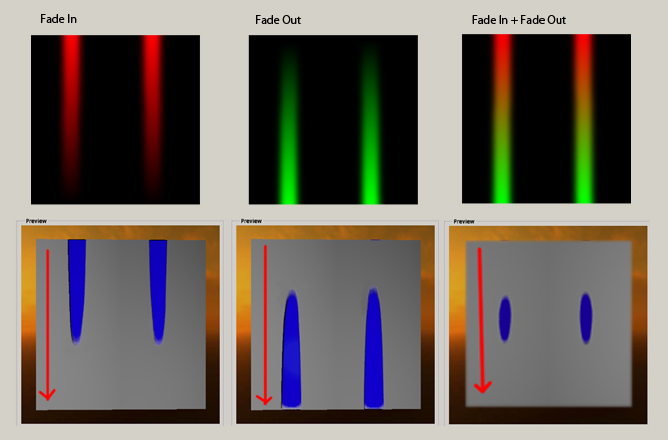
FadeInStart, FadeInEnd, FadeOutStart, FadeOutEnd
Parameters for how the particles in the rendered volume fade in out. All distant are measured as z-distance from camera.
IterationNum
The number of particles that If it has a fraction (eg 13.45), the fractional part (eg 0.45) determines the alpha of the last iteration. (to allows fading iterations)
Color
The color the particles are modulated by.
GravityVelocity, WindVelocity
Two different velocity values for each of the particles.
RotateVelocity
The speed at which the particles rotate around the center of the volume.
GravitySpeedRandomAmount, WindSpeedRandomAmount, WindDirectionRandomAmount,RotateSpeedRandomAmount
The random variations are added to any iterations after the first! Valid values for all amounts are 0 - 1 (can be others, but not recommended).
What it does it that any subsequent iterations will have the vector updated like: vector + vector*random amount. So if the vector is (0,1,0.1) and if the random amount is 0.1, then any subsequent iterations will have values between (0, 0.9, 0.09) - (0, 1.1, 0.11). Wind direction random is a bit different, what is does is that it rotates the vector (around all axes) by around amount. Wind random amount of 1 means, it can rotate into any direction of a sphere, 0.5 means half a sphere, 0.25, quarter of a sphere and so on.
Also note that the random values are psuedo-random, this means that they do not change depending on play through, but they are always they same. So if it looks like something in the editor, the random distribution will look exactly the same when you view it later in the game.
RotateSpeedRandomBothDirs
If the rotations can go the opposite direction too.
Lens Flares
Overview
Lens flares are a bright spot that appear at the center of a strong light source.
Lens flares are created by light entering through a camera objective and reflecting multiple times off the surface of the numerous lenses inside it, creating several recognizable artifacts.
The 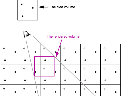 is needed to display this content.
Flare Types

Each lens flare consists of a few different kind of flare types that can be active at the same time.
Flare
A normal flare that rotates slightly depending on its position on the screen.
Anamorphic flare
A flare that stretches in either horizontal or vertical direction. The anamorphic flare stretches out more the closer it gets to the edge of the screen.
Multi Iris
A line of small iris shaped artifacts stretching toward and away from center of the screen. The brightness/size/sub-texture of each individual iris is randomly determined by the seed of the flare.
Flare Type Settings
Material
The material of the flare type. Additive blend and depth test disabled are recommended for best result.
Color
Size
The size of the flare type. A value of 1.0 means that it covers the whole screen.
General Settings
Outer Field of View
The angle in degrees of which the flare should be visible. The brightness fades from 0-100% between Outer and Inner Field of View.
Inner Field of View
The angle in degrees of which the flare should have full brightness.
Min Range
The minimum range for when the lens flare is visible. A value of -1 means that the camera can never be to close.
Max Range
The maximum range for when the lens flare is visible. A value of -1 means that the lens flare has an unlimited range.
Size change based on distance
A real value between 0-1 that determines how much the screen size of the lens flare should change the further away it gets. A value of 0 means that the flare always has same size on the screen.
Glare Settings
Lens flares can be used to blind the camera. Either if the camera is looking directly at the lens flare or if the lens flare is pointed toward the camera.
Glare Brightness
How much the camera will be blinded.
Glare Stare At
How blinded the camera will be by looking directly at the lens flare.
Glare Field of View
The angle in degrees of which the lens flare should blind the camera. The camera will be more blinded the more the lens flare pointed at the camera.
Glare Range
How close the lens flare has to be to blind the camera. The glare brightness fades out between the minimum and maximum value. A value of -1 means unlimited range.
Multi Iris Settings
Mul MultiIris with Glare
Toggles whether the strength of the Multi Iris line should be affected by the glare amount.
MultiIris Count
The number of irises in the Multi Iris line.
MultiIris texture atlas grid
The material for the Multi Iris line can be a texture atlas with many small sub-textures on it. The texture grid selects how many sub-textures there are and how they are divided on the texture atlas. A texture with the size 128×128 and a sub-texture size of 64×64 would have a value of (2,2).
Occlusion Settings
Shrink when Occluded
Toggles whether the lens flare should shrink or fade out when it gets occluded.
Source Size
3D Vector storing the size of the occluder for the lens flare. Will be displayed as a green wireframe box.
Use parent mesh for occlusion
Uses the mesh of the parent instead of the Source Size box as an occluder.
Gamma Correction
Overview
There are two types of gamma correction. The first one makes sure that the image is displayed correctly on a computer screen. The luminance of a computer monitor is not linear, to compensate this gamma correction is applied to each pixel. This is done by adjusting the curve of the image to make all the pixels brighter, the shadows get affected the most and the highlights the least. When the image gets displayed on the monitor the inverse curve is applied and all the pixels are displayed at their original luminance. This is something that is done automatically by digital cameras and applications like Photoshop. 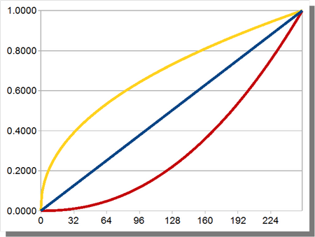
The second type of gamma correction makes sure that all light calculations are perform in linear-space. Since textures created in Photoshop are saved in gamma space they need to be converted to linear-space before lighting is applied to them. This is done by applying the inverse curve that the monitor uses and then multiplying it with the color and brightness of the light source.
Links
HDR Rendering
Overview
A normal computer monitor can display display colors in the range of (0-255) per color channel. This adds up to around 16.77 million unique colors.
With HDR Rendering the number of colors per channel is increased to 65565. This is increases the precision and quality of dark/grey tones and it also gives the ability to have colors that are brighter than the monitor can display.
Having colors that are brighter then what the monitor can display would be a waste. A technique called Tone Mapping is applied to the high precision color to covert it to a range between (0-255) so that the monitor can display it.
All light have a brightness setting so that they can be brighter then 1. The overall range of the brightness of a level should be around (0-10) for best result. Before HDR was implemented it was a in the range of (0-1). You can think of light brightness as light bulb energy. A brightness of 6 = 60 W, 4 = 40W.
Tone Mapping
Tone Mapping is a technique to convert colors from high precsion to colors visible on the monitor. The algorithm starts by scaling the luminance of the image by the exposure of the camera, making the whole image darker or brighter. It then uses a function to map data in the domain of (0-Unlimited) to values between (0-1). The function used in the engine is called called Uncharted Tone Mapping, from the game Uncharted 2. It increases the contrast of the image by making the dark colors darker and smoothing out the highlights. After that all colors are scaled by a white point, clamping all colors above the white point to 1.
Variables
MiddleGrey | A real value that sets what should be considered the middle grey value.
Exposure | The total light that is allowed through the camera, increasing this value makes the image brighter. In the range of -10 to +10.
WhitePoint | A real value that sets which value that should be considered the brightest.
Exposure Area
Overview
A area that changes the tone mapping parameters when entered. Used to simulate automatic correction of exposure that occurs when eyes get used to bright/dim lit environments.
Variables
Position | The world position of the trigger area.
Size | The size of the area that triggers the change.
Exposure | The total light that is allowed through the camera, increasing this value makes the image brighter. In the range of -10 to +10.
WhitePoint | A real value that sets which value that should be considered the brightest.
TransitionTime | The time it takes for the new exposure to apply.
Color Grading
Overview
Color grading is a way to map the color of a pixel to another color. This can be used to change the brightness, contrast, hue, saturation, … of a whole image.
It is possible to smoothly fade between two different grading templates.
It uses a small 3D texture with a color as input and another color as output.
grading.jpg
Creation Guide
Requirements
Photoshop NVIDIA Texture Tools for Adobe Photoshop
Setup
- Take a screenshot of the game with color grading disabled
- Open the screenshot in Photoshop
- Drag and drop the default grading texture on the canvas (redist/core/textures/grading_default.dds) or (Default Grading Texture )
- Place the color strip anywhere in the image
- Flatten the image to merge all the layers
- Select "Image > Mode > 16 Bits/Channel" in the top menu
Adjustments
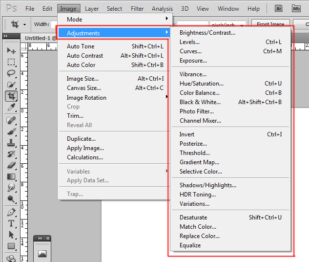
Use any of the options in "Image > Adjustments" These can be used to change the brightness, saturation, contrast and so on Any changes you see on the image in Photoshop will carry over to the game
Layers
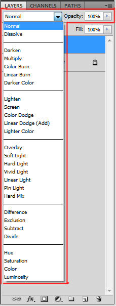
It is also possible to use the any of the layer blend modes There are two kinds of layers allowed:
- Solid color
- Dupilcate of the first layer
It is possible to duplicate the first layer and make adjustments to it and then blend it The use of Layer Masks is allowed as long as they are generated from the image and not hand painted
Saving
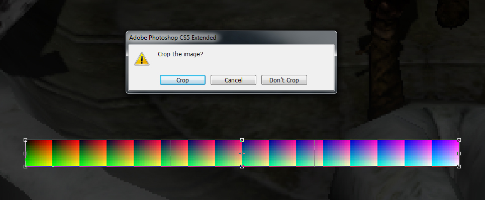
- Crop the color strip from the canvas, make sure the resulting image is 256×16 px
- Select "Save As…" and set the format as "D3D/DDS"/".dds" and save it in the folder "redist/textures/colorgrading/"
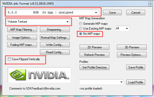
- In the DDS format settings select "8.8.8.8 RGBA 32 bit | unsigned", "Volume Texture", "No MIP maps" (Ignore the picture, use 32 bpp!)
Billboard Group
Overview
A group with multiple billboards. Batching them together and rendering them at the same time.
All the billboards in a group must have the same material, but all other parameters can be different.
Alpha sorting is performed internally within the group. But alpha sorting with external billboards and billboard groups is performed as usual. Because of this the billboards in agroup should not be to spread out, a maximum radius of 5-10m is recommended.
When selected the Billboard Group will show the combinded bounding volume of all the billboards.
Settings
Material | The material which will be used to render all the billboards in the group.
Liquid Trickle
Overview
A shader effect to simulate liquid spreading out over an object. The amount of liquid is controlled by a texture and a variable called LiquidAmount. The variable can be set via scripting or be updated automatically over time. The texture is used to mask out where the liquid can spread and in which order it spreads, it is also used to determine how the liquid fades away.
Texture
To create a liquid texture map two color channels must be used. The red channel is a gradient mask that controls where the liquid spreads and the order of the spread. The brighter the pixel is the earlier it is covered in liquid. If the pixel is set to (0,0,0) the liquid will be completely masked. The green channel is used to determine in which order the liquid will fade out. Fading out can be turned off in the material editor.
When saving the texture it should be exported as a compressed 3dc dds. If the quality for the texture is not good enough then the texture can be saved as a tga, for this to work the red channel has to be copied in to the alpha channel and the green channel to the blue channel.
Scripting
For some effects the liquid amount can be controlled automatically by the time. But scripting can be used to create some other interesting effects. One effect could be to set the LiquidAmount variable to correspond to how much of an object is below the water surface and then slowly lower the LiquidAmount to simulate it drying. Scripting can also be used for showing blood when a character is hurt or if oil starts leaking when triggering a trap.
When a material should work with scripting it is a good idea to set the LiquidTrickleFadeIn parameter to 1 so that the LiquidAmount variable works as percentage instead of time.
Depth of Field
Overview
Depth of Field describes which part of the screen should be in focus and sharp. DOF is the distance between the nearest and farthest object in the scene that should appear sharp.
Settings
Focus Start | The nearest distance to the camera that an object has to be to be sharp. Any closer and it will be blurry
Focus End | The farthest away an object can be and still be sharp. Any further away and it will start getting blurry
Falloff | How fast the object should get blurry when it is closer or further away then the focus plane. The blur distance is caluclated as (Focus End - Focus Start) / Falloff
File:Depth of field diagram.png
Distance Culling
Overview
Removal of objects that get to far away from the camera. Objects are removed based on how big they appear on the screen. The objects are gradually faded out until they are removed. Solid objects dissolve and translucent objects have their alpha faded.
The default setting is that all objects are faded out when distance culling is activated. Important objects and objects that make up the silhouette of the level should have distance culling turned off.
Distance culling should only be activated on outdoor levels where occlusion culling is not as effective.
Settings
Distance Cull Active | If distance culling should be used on this level
Distance Cull Min Range | The minimum range before objects start fading out. This is important to set so that very small objects dont get culled to early
Distance Cull Screen Size | How small an object has to be in screen size to be culled. A real value between 0.0 - 1.0. If set to 0.1 then any object that is smaller then 10% of the height of the screen will get culled
Distance Cull Random Size | A random value unique to each object that is added to the screen size. This shoudl be used so that not all objects of the same size are removed at the same range
Culled By Distance | A variable set per object that specifies if the object should be affected by distance culling
