HPL1/Content Creation Chapter 3
Contents
- 1 3. Creating maps
- 1.1 3.1 Rooms
- 1.2 3.2 Portals
- 1.3 3.3 Lights
- 1.4 3.4 References
- 1.5 3.5 Name parameters
- 1.6 3.6 Animations
- 1.7 3.7 Colliders
- 1.8 3.8 Sound Entities
- 1.9 3.9 Sound blockers
- 1.10 3.10 Start positions
- 1.11 3.11 Areas
- 1.12 3.12 Billboards
- 1.13 3.13 Beams
- 1.14 3.14 Particle systems
- 1.15 3.15 Workflow
- 1.16 3.16 Optimizations
- 1.17 3.17 Issues
3. Creating maps
Maps in the HPL-Engine are created using rooms and portals to limit the amount of objects being rendered and the system works something like this:
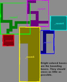
1. First it is check what rooms the camera (player) is in. This is checked by using the bounding boxes of the rooms. A bounding box is generated by the engine by the making an axis aligned box that exactly covers all the vertices of the main room geometry. Axis aligned means that the height is parallel to the y-axis, width to the x-axis and depth to the z-axis. The boxes are not rotated in any way. The bounding boxes can be seen when pressing 2 in the sceneviewer. The rooms camera are in a placed in a render list.
2. When the engine has determined what rooms the camera is in then it starts checking what portals can be seen in these rooms. This checking only checks the field of view and cannot see if any object is blocking a portal.
3. For each portal that can be seen, the engine checks what room the portal connects to and then it places this room in a render list (if the room is all ready in the list, it is skipped).
4. In the connected room the engine checks what portals the portal that lead to this room can see, then checks if they are in the field of view of the camera. If a portal is claimed visible then it is looped from point 3. This continues until no portals are left to check.
3.1 Rooms
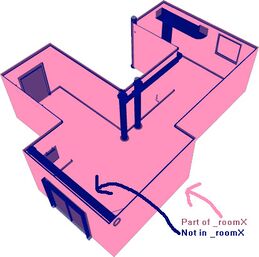
When making maps you must divide the entire map into rooms. A room can be an outdoor area, a corridor, several rooms, a room (off course), etc. To make a room in Maya all the main objects (more on this later) in the room should be grouped in a “_room#” group, # being a string of characters, for example: “_room1C”, “_room3F4”,”_roomDeath”, etc. Note that the “_” character is forbidden to use in the name except as a starting character, which is a must.
The easiest way to do this is to create all the main geometry for the room with the prefix “room” + room number + “_” (i.e. room1_pBox22) and then place all these under a “_room#” node in the hyper graph editor. Do not name the objects with the prefix “_room”. All names starting with “_” are special objects and the importer deals with these in a special way.
If all object names in a room has the same prefix it is easy to see in the hyper graph editor if some objects are placed under the wrong node and so on. So do it like this to avoid confusion and more work then needed. In the hyper graph nodes can just be placed under the right room by dragging them with the middle mouse button.
To make this as simple as possible the only things that are needed to be in a room is the geometry (no lights allowed) defining the room. This means most likely the walls in the room. All other stuff (except the portals) do NOT have to be placed in the “_room#” group. They will be added to the rooms they are in at load time. See below for example.
Note that objects that are in two or more rooms at the same time demand some extra cpu power at runtime so avoid this when it is not needed. Note that static geometry can be placed either in a “_room#” group or not (it does not have to be considered main geometry). However, lights and references are forbidden in room groups!
Another very important thing is that the bounding boxes of the rooms should not overlap and if it is must then the boxes should overlap as little as possible. Overlapping bounding boxes = major speed loss. See below for example.
3.2 Portals
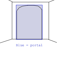
A Portal is a rectangle that defines the connection between two rooms. A portal must be a one-sided rectangle and cover the hole between two rooms completely. It is not a problem if the portal is bigger than the hole, but it should fit a good as possible. This means that a hole between two rooms can be a round, triangular or any arbitrary form. A rectangle must still be used even if the hole is not rectangular and the hole must be covered 100% even if the fit does not get perfect.
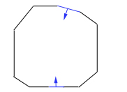
The portal must be placed in the “_room#” group that it belongs to. The normal of the rectangle must be facing the center of the room it belongs to and not the room it connects to.
Portals are named “_portal#_room#” + “_#” for each portal that can be seen from this portal.
The first # is the number of the portal; this must be exclusive inside the room the portal is in (i.e. there cannot be two “_portal55” under “_room4”). Two or more rooms may have portals with the same number though (i.e. There may be a “_portal4” under “_room4”, “_room2” and “_room1”).
The next # is the number of the room that the portal connect to, so a portal name could be “_portal2_room4”. This is a portal with the number 2 that connects to “_room4”.
The following optional texts are numbers of portals which can be seen from this portal. I.e.: “_portal4_room3_2_34” connects to “_room3” and in room 3 the portals 2 and 34 can be seen. “Can be seen” means that if you where to peak through the portal there is someway that these portals could be visible.
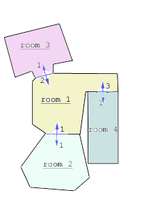
In the image above the circumstances are as follows:
- Room 2 - Portal 1 can see portal 2.
- Room 3 - Portal 1 can see portal 1 and 3.
- Room 4 - Portal 1 can see portal 2.
- The portals in room 1 can see no other portals.
The names for the portals will be the following:
- Room 2 - Portal 1: “_portal1_room1_2”
- Room 3 - Portal 1: “_portal1_room1_1_3”
- Room 4 - Portal 1: “_portal1_room1_2”
The portals in room 1 will have the following names:
- Portal 1: _portal1_room2
- Portal 2: _portal2_room3
- Portal 3: _portal3_room4
Note that the sketch of the portal connections does not have a good design since the bounding boxes of the rooms overlap! This should be avoided if possible (and in the currently version overlapping bounding boxes will probably lead to bugs.)
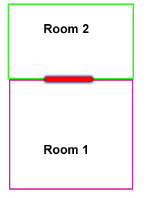
When placing portals it is important that they are that the edge of the room or where two or more room bounding boxes overlap.
The red rectangle above marks where the portals for both rooms should be placed when two rooms lies side by side. Not that the portals are much thicker then what they are in the engine. The reason for this is that player should not be able to be in for example Room 1, be looking at Room 2 and not see the portal belonging to Room1. This means that Room 2 will not be rendered.
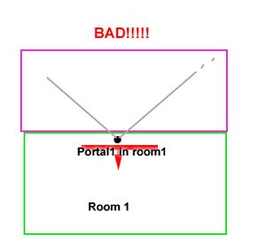
As seen in the image above the player is symbolized by the black dot and has sight into the purple room; however the portal is behind the player so the purple room cannot be seen. However if the two rooms overlap so that the edge of the purple room is close to the portal then it is okay!
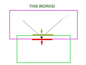
As seen in the image above the player is inside the bounding box of the purple room as well so it doesn’t have to have to see the portal. The dark yellow rectangle is where the portal in the purple would be placed.
Note that that the three images above all show bounding boxes and not room geometry! Another thing to note is that overlapping bounding boxes should be avoided when possible since it can result in a lot of unnecessary rooms being rendered. When creating maps remember to press 2 in the map viewer to debug and optimize portals and rooms.
3.3 Lights
3.3.1 General
If the light should be dynamic (this means attenuation, angle or position changes, NOT color change), use the prefix “dynamic” on the light name. I.e.: “dynamic_PointLight1” will be a dynamic light.
Note that lights should not be part of room group hierarchy.
3.3.2 Point Lights
Point Lights have the following attributes:
| Attenuation | The range of the light. |
| Color | The color it casts. |
| Specular | How much specular light it emits. 0 – 1. |
| CastsShadow | If the light casts shadows or not. |
| FalloffImage | The rate at which the light goes from full color to black. Default = linear. This is represented as a 1D image (meaning height is 1). The far left is the max light intensity and the far right is the lowest (should be black). The width must be a power of 2. |
Color is set as normally in the 3D editor, but because the collada exporter handles light very badly, attenuation and specular has to be set using the scale of the light. This means scale X = attenuation and scale Y = specular. Attenuation has a value from 0 to eternity specular has a value from 0 to 1.
If the light casts shadows or not is also set by the scale. Scale Z 0 means no shadows are cast and 1 means the light casts shadows.
Falloff is set in the light entity file (light).
3.3.3 Spot Lights
Spot lights have a few more properties than point lights, these are all of point light’s plus:
| FieldOfView | The size in degrees of the cone that casts the light. 0 – 180. |
| Aspect | How much larger /smaller the width of the cone is when compared to it’s height. 1 = same size, 0.5 = half size, 2 = double size, etc. |
| NearClipPlane | Objects under this distance will not be lit. 0 – inf. Normally around 0.1. |
| ProjectionImage | This is the image that the light projects, RGB channel represent color of the light and it must have an alpha channel that decides the specular influence. The borders of this must be 100% black and it must have power of 2 size. |
| ProjectionAnimMode | If the projection image is an animation and if so the mode used. If it is an animation then the syntax for image is: [name].[ext]. And then the textures in the animation must be named [name]01.[ext], [name]02.[ext], etc. Values can be “None”, “Loop” and “Oscillate”. |
| ProjectionFrameTime | The time in seconds each frame is shown if it is an animation. |
Color and Field of View are set as normal. Attenuation is set using scale X. The rest of the attributes are set in the light entity file, light.
MAYA TIP: In the light’s locator scale to 55.5 and then set all the scale directions when setting attenuation. Now the arrow of the locator will show the length that light reaches.
3.3.4 Light Entity file
Light entity file lets you set some general properties for a light. The syntax is like this:
<LIGHTENTITY>
<MAIN
ProjectionImage = "my_image.ext"
    [other variables with the same names as above]

/>
</LIGHTENTITY>
The extension of these files must be “lnt”.
The properties in the file will over-write previous values (such as those set in the editor). All of the properties, except ProjectionImage, can be excluded and will then be given default values.
To set a light entity file to a light use the following syntax when naming the light in the editor:
[dynamic (optional)] [ _ ] [entityfile] [ _ ] [lightname]
| dynamic | Add “dynamic” infront of the name if the light is going to cross other portals other than the one it starts in. |
| entityfile | The name of the light entity file. May contain “_” in the file name. |
| lightname | The name of the light. |
Examples:
dynamic_mylight
Will create a light that is going to move and does not have any entity file.
dynamic_my_light_file_mylight
This is a dynamic light that loads data from “my_light_file.lnt” and is named “mylight”.
my_light_file_mylight
This is a static light that loads data from “my_light_file.lnt” and is named “mylight”.
3.4 References
References are used to add external objects to the map.
When referencing to an object you must use a special reference file and it is very important that the file only contains one object. If not the referencing will fail. This special reference file will be called reference object (and nothing else) for the duration of this chapter.
Another extremely important thing is that the reference object looks exactly the same in size and placement as the file you want to reference to. It may not contain any rotation, scale or translation and if the model needs to have an offset the it is very important that the pivot is at (0,0,0) in the reference object. When you reference to a file the engine will place the referenced file with its origo at the reference object’s pivot. This is one reason why you should always try to center your object in the model file.
Maya references
In the options for “create reference” lock and group must be unchecked. When creating further copies of the reference remember to have set to instancing in “duplicate” options. Also turn off namespaces and be sure to name the node in the reference object correctly and with a unique name!
Max Xref
Simply create an xref to the reference object.
Naming
NOTE: When naming the several grouped objects, it is the group that must be named! You can also create references by just importing normal geometry and naming it correctly (note that the imported geometry only should be one object or several objects in group). The syntax is the following:
_ref_[file]_[name]
| file | The entity file to load. This may contain “_” and must not contain any extension (i.e. “.ent”). |
| name | The name of the object in the game world. |
Example:
_ref_wooden_box01_Box01
This will create an entity for the file “wooden_box01.ent” and it will have the name “Box01”.
Below are descriptions of the different reference types. (Read this as if there is only one type of object you can reference to and that is the entity.)
See the following tutorial for an explanation of entities, how they work and why.
3.4.1 Static models
Do not read this! This is only for the programmer’s reference. Ignore as if it didn’t exist!
The name of the reference has the prefix “static_”. This should only be used for animated static geometry on the map such as fans, machinery, etc. For non animated static geometry normal geometry should be used. The animation for these models must not change during run time and they must be placed in such a way that they never touch more rooms during animation then they do in bind pose. The referenced Maya .mb file must have the same name as the model file (.msh, .dae, etc) that you want added to the map.
3.4.2 Entities
The name of the reference doesn’t need any prefix. Any name will do. These are things like monsters, item, etc. It is what ever the game wants them to be. These references (the referenced .mb file name) do not refer to model files but rather an entity file. The entity has the extension “.ent” and is a simple text XML file. This xml file can contain info that is mostly game specific.
As an example, a _ref_my_woodbox01_box01 reference added in the 3D editor does not point to a model file named my_woodbox01.dae/.mb/.3ds etc, it points to a .ent file named my_woodbox01.ent and this file contains the properties, special functions AND also contains information on what model file to use for the reference!
More on this in entity files.
3.5 Name parameters
Because some options are unavailable (or unexportable) in 3D editors, some settings have to be set by adding certain text to the names of objects. A parameter is written with a “_” in front of it and can not be the first text in the name. For example:
“Ball04_noshadow_nocollide”
“Ball04_noshadow_”
are both legal.
“_nocollide_Ball04” is not legal! But you can write ““nocollide_Ball04” by exluding the _.
The following is a list of the parameters all objects types can have.
Geometry / References:
| noshadow | No shadows are cast from this object. |
| nodraw | The object will not be visible but it's mesh will be used as a collider. |
| nocollide | Nothing will collide with this object. |
| nocharcollide | Objects will collide with it but not the player. |
| nosoundblock | Sound will be unaltered through this object |
| soundblock | Sound will be lower through this object. |
Colliders:
| soundblock | Sound will be lower through this collider, example: _collider_box_collider1_soundblock. |
3.6 Animations
Never use animations directly in maps, instead reference to static object or to entities with animations.
3.7 Colliders
Colliders are added in exactly the same way as described in chapter 2.4. There are some differences though. One is that all geometry will be turned in to collideable meshes unless the “nocollide” parameter is specified, so if you want to simplify, for example, a statue mesh, the statue mesh must have the “nocollide” argument.
Another difference is that colliders in a scene (static, imported models) are not linked with any entity like ones in a model file (referenced models) and therefore do not have any physics material linked to them. This means that if you want the collider to have a physics material other than “Default” you must assign a material (a material with texture and stuff) to it. This material should then have the physics material you want to use. For example if you want to make a simplified collider for a statue (or maybe several colliders) you should assign the same material as the statue to the collider(s).
When creating maps there is an additional collider called “_charcollider” that can be used. This collider will collide only with the player character, which can be useful if you want to block the players path but not have objects bounce of something invisible.
3.8 Sound Entities
Sound entities are use to place sounds on the map. To palce one is really easy. Just name any node (geometry or dummy object):
_sound_[entity file]_[name]
| entity file | An “snt”-file containing data for the sound. More about this in the [[HPL1/Content Creation | HPLHelper chapter]]. Note that this name may have “_” in it! And DO NOT specify the extension (.snt). |
| name | This is what the sound entity will be called in game. |
Examples:
_sound_test_drops_mysound1
This will create a sound entity named “mysound1” that uses the file “test_drops.snt”.
3.9 Sound blockers
Sound is blocked by certain bodies in the world. When the sound is blocked by something it gets lower just like in the real world. These are the “rules” that apply for sound blockers:
- All geometry that is collideable and part of a room group is automatically set as a sound blocker. This is all the geometry that defines a rooms bounding box. If one of these objects should not be a sound blocker then the parameter “nosoundblock” must be used!
- All other objects and entities that are not apart of the room group are automatically assigned as none sound blocking. If you want one of these object to block sound you must use the “soundblock” parameter or set “BlocksSound” in the entity file to “true”.
- As default Scene colliders (not colliders in models) are none sound blocking. Setting the parameter “soundblock” will turn sound blocking on.
3.10 Start positions
These are used to set where in the world the player/camera should start. Any object can be used to specify a start position the only important thing is the naming which has to be:
_start_[name]
| name | The in game name of the start position. May contain “_”. |
Example: _start_my_start1
This creates a start position with the name “my_start1”.
To specify direction just rotate the object, scale may not be used! If no rotation is set the player/camera will look down the negative z-axis (y-axis for 3ds users).
3.11 Areas
Areas can be used for several engine and game specific tasks. The syntax is:
_area_[type (optional)]_[name]
| type | This is game specific information, should be “script” mostly though. See [[HPL1/Script Reference | script reference]] for scripts that uses specific types. |
| name | This is the area the start will have when you try to access it. |
Types
- script - The regular area type for most scripts.
- damage - Specfic area to be used with certain scripts dealing with damage to player, entites and objects. Properties set by script.
- liquid - Specific area for setting up liquids(water and so on). Properties set by script.
- stick - An area that will let other objects “stick” to it, used for specific stick scripts. Properties set by script.
- force - An area that will apply a force to the player, entities and objects in it. Properties set by script.
- link - An area that will trigger the loading of a new level/same level with a new starting point.
- save - Will save the game when the player interacts with it.
- ladder - Attaches the player when he interacts with it, the positioning, size and rotation gives the ladder it's main functions. Specific sounds and such is set by script.
- mess - An area that displays an examination message. This can also be done by script on a normal area/entity.
special syntax for this area: _area_mess_cat_entry_name
cat = translation file category.
entry = translation file entry.
name = optional, for uses of scripting "cat_entry_name" is used.
An area is created in exactly the same way as you would create a box collider. Mostly the area doesn’t need the material though.
If the area does not have a type then it is only considered an engine area and will not have any game specific propose.
3.12 Billboards
Billboards are rectangles that always faces the camera, these can be used for a lot of things like light flares, grass, etc. The syntax for placing a billboard is the following:
_bb_[entity file]_[name]
| entity file | Entity file containing data about the billboard, may contain “_”. |
| name | The name that will be used in game. |
Scale x is width, scale y height and scale z offset (might help to use a 1,1,1 box has place holder to get a hunch in the editor how it will look in game). The orientation (rotation) defines the axis of the billboard (this is only used for Axis-billboards).
The entity file looks like this and is a file with the extension “.bnt”:
<BILLBOARD>
<MAIN
Material = "my material.mat"
    [other variables with the same names as below]

/>
</BILLBOARD>
It may contain the following variables:
| Material | The material (.mat file) that the billboard has. String |
| Type | The type of billboard. “Point” or “Axis”. Point means the billboard is rotated around its center and axis means that it is rotated round its axis. String |
| UseOffset | If the billboard should be offset closer to the camera when rendering. Boolean. |
| IsHalo | If the billboards is a halo. This means that it will loose strength if the source is blocked from view. Boolean |
| HaloSourceIsParent | If the parent entity of the billboard (must be a submesh) will act as light halo source. Boolean |
| HaloSourceSize | If the parent is not source then this will use as size of the source. Center of the source is the position of the billboard. Vector3 |
Important halo information: There can only be one billboard attached per submesh!
3.13 Beams
Beams is a flat image that is repeated from a start to an end point creating for example a laser beam. The syntax for placing a beam is the following:
_beam_[file]_[name]
_beamend_[name]
| file | The entity file containing data about the beam, may contain “_” in the name. |
| name | The name that will be used in game. |
A beam is made up of two parts in the editor, one _beam for the start position and one _beamend for the end position. It's important that the beamend has the same name as the beam.
The entity file looks like this and is a file with the extension “.beam”:
<BEAM>
<MAIN
Material = "my material.mat"
    [other variables with the same names as below]

/>
</BEAM>
It may contain the following variables:
| Material | The material (.mat file) that the beam has. String |
| Size | “X Y”.X= the thickness of the line, width of texture used. Y = the length that one texture height takes. Vector2 |
| TileHeight | If Size.x should be used and texture tiled. Boolean |
| MultiplyAlphaWithColor | If the color should be multiplied by alpha. Makes some things simpler. Boolean |
| StartColor | “R G B A” Color at start. Vector4 |
| EndColor | “R G B A” Color at end. Vector4 |
3.14 Particle systems
Particle systems are used for effect such as fire, smoke, etc. The syntax for placing a particle system is:
_ps_[particle system name]_[name]
| particle system name | Entity file containing data about the billboard, may contain “_”. |
| name | The name that will be used in game. |
Particle systems are created with the Particle Editor, which is documented here and a tutorial is available here.
3.15 Workflow
What follows is a suggestion on the workflow used when creating a map for the HPL engine.
3.16 Optimizations
The following “tips” are very important to follow as good as possible since they can improve the framerate quite a lot.
- Set small objects to “noshadow”, since shadows on smaller objects are not noticeable.
- Set “noshadow” on objects that cannot cast a shadow on anything. This is for example a floofor if there is no floor below. Think about this when designing maps and quite some framerate can be gained.
- Do not let several large objects that are not close together be apart of the same mesh object. This is for example the 4 walls in a room. Separate these so they are 4 individual objects instead of one.
- While it is bad to put many BIG objects together. It is really good to put many small together. If you have 20 static cans spread over the floor in a room it is a lot better to collapse them all together to a single object (beware: grouping is not the same as collapsing, Maya word for this is unify). However do not collapse several small objects that are spread over an entire level. The objects should be close together (like on the same floor in a room.
- The number of lights is not the biggest problem. The biggest problem is overlapping lights. Overlapping means that the bounding boxes from 2 lights intersect. Try to have at most 3 overlapping lights and mostly 2 lights overlapping. If the lights don’t cast shadows it is okay if more lights overlap.
- Highpoly meshes should have collisions turned off and use colliders to simulate the shape.
3.17 Issues
- If a room is totally self contained (like a cube with the sides inverted) then the shadows will be messed up. You can fix this by detaching one of the walls or just turn off shadows for the room. Since no shadows will be visible from the room turning of the shadows is the best bet.
- Two faces in the same object may not share the same vertices, even if the order is inverted! This means that double sided polygons are not supported! This only applies to geometry that cast shadows though.
- An edge may only have one or two faces! If this is not followed shadows will be messed up.
